I was wondering if you could share some more information about your BLDC Servo project. You had an open source board design, right? How well does it work? What are the specs? I’d love to hear some more details. I’ve seen a few of the videos on youtube but was hoping we could discuss it a bit here
Sorry for the long delay, but yes I’m very happy to share more details.
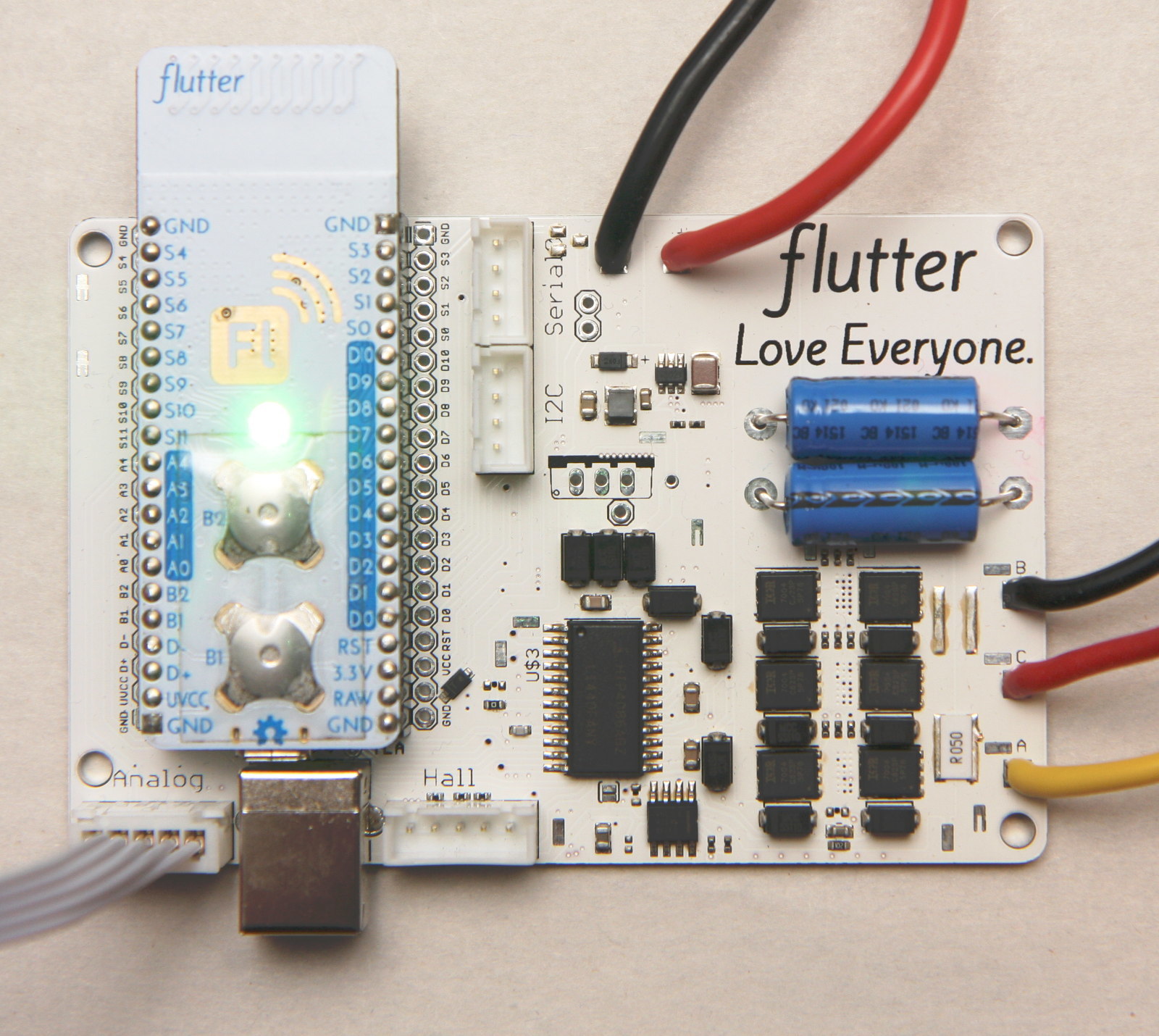
So for reference for others, the BLDC driver we are talking about is this one:
The source files are here:
The Readme has some good details on the device, though it could stand to be updated.
The biggest thing I have learned since writing the Readme is that the originally planned power capability of 1kW is a lot for those FETs. For burst currents that should be fine, but I’d target more like 300-600 Watts with this FET package. However if you know EAGLE the board can easily be changed to use larger FETs that will better handle higher currents.
Over Christmas break I assembled Version 2 of the board, which is what is shown in the photograph above. Version 2 fixed some major problems with Version 1 so the board now works without hardware patches, and adds a FET to control an external fan.
My plan for this hardware is to make a modular FET driver for the kind of robotics I do with home 3D printers. I want to make it possible to buy a brushless motor from HobbyKing, add a magnet to the shaft and attach an angle sensor, and then servo that motor (that is, have closed loop speed, position, or torque control) with this controller. Then you can also design 3D printed gearboxes (planetary or spur gears) that let you turn this into a giant hobby servo type setup.
This is the type of motor I’m targeting:
or
(Currently I have the second motor)
The latest hardware all works, in that it switches the FETs properly and the current sensor works. The firmware I have written is only rudimentary test code that will spin my motor with some basic square wave switching of the coils.
The real magic for all this is the position sensor. I’m using a low cost magnetic angle sensor designed for brushless motor position sensing applications, and have devised a simple board that screws on to the Hobbyking 5008 motor from the second link above.
When I first tried the sensor, it didn’t behave as expected and I could not derive motor angle from the output. As it turned out, I did not buy the correct magnets. The sensor needs a diametrically magnetized magnet on the shaft to sense the angle, and I stupidly purchased normal axially magnetized magnets. I worked on it for a few hours this past Thursday evening and got that figured out. I also discovered a slight mechanical error in my sensor layout, which is fixed.
I have the correct magnets arriving tomorrow, and will test them soon. If they work I’ll spin boards for the updated sensor.
Once you can accurately measure the position of one of those motors, some basic servoing code should be pretty straightforward. Then I have several robots in mind that I want to build with the motors to further prove the controller.
You may notice that the controller currently uses Flutter as a microcontroller. Flutter uses an Atmel SAM3S1A 64MHz Cortex M3 CPU and runs Arduino code. That’s quick for my prototyping because I have a bunch of them, but I hope in the future to integrate that same CPU directly onto the motor controller, eliminating the need for Flutter hardware and lowering the cost.
Once I have proven that the sensor works and I can servo a motor, I’d like to produce a batch of these controllers for myself and other interested parties. They may be something like $100 apiece.
Down the road, I also have some ideas about better ways to make brushless motors for low speed applications, and want to use my controller to explore that.
Another thing worth mentioning is the design reasoning for the controller. I use a “dumb” MOSFET gate driver with no built in motor control so that all the control is done in software. This allows us to make a lower current software-compatible version of the board that lacks the gate driver and uses P channel FETs on top.
There’s probably more I could say, but this is already long and feels disorganized.
It sounds great - you mention that you use flutters because you have them on hand, but I’m not really familiar with them, but I assume it’s basically a different kind of arduino? I’m wondering what the requirements are processing-wise and what the 100$ price point is based on. Is the 100 for a small production run? Does it include the encoder? And so on. It would seem that every dollar saved on this kind of essential component would have a massive impact if one was to build a system that used hundreds of these little motor packages.
What are the control requirements? Will each board have firmware and essentially work with just some kind of position input or does it require some kind of “mother board” that handles the calculations?
I’m thinking if it’s possible to make little standalone units that just require power and some simple input signal, at a low cost, that would be a great improvement over currently existing technology.
Have you looked into how the price would change with lower/higher power capabilities of the drive board? Maybe a lower power but cheaper version would be even more useful, as you also seem to suggest at the end of your post.
There’s certainly a lot to talk about and discuss at least. To be honest, I only have quite basic knowledge about the function of feedback driven BLDC motors, but every project I’ve seen that used them, even ones made by “amateurs” were very impressive. It seems the main issue is going to be cost - simple stepper motors would probably still be more viable in many low budget situations.