Hi Everyone,
I’m new to the site, and I don’t have much background in making/designing small-scale rover-type of things… but one thing about the Suspension Design for Rover has been bugging me. I have a little experience in off-roading and mini-baja build… so some things I say might not be so valid for this smaller design haha. Might just be over-thinking it.
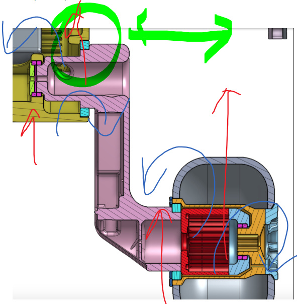
As a preface, lets recap the ideal bearing:
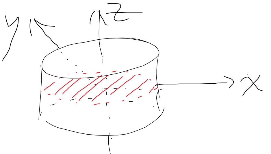
An ideal bearing should only take load/force in the x-y plane, where it rotates freely about the z-axis. It should not be subject to any axial force in the z-axis, nor should it be subject to any torques along x or y axes… torque in the z-axis is of course allowed, and that is how it spins. When I say “should not”, i’m talking about potential for warping the bearings and causing un-even wear… that is why you should always get your new tires balanced by a mechanic before installing them on your car.
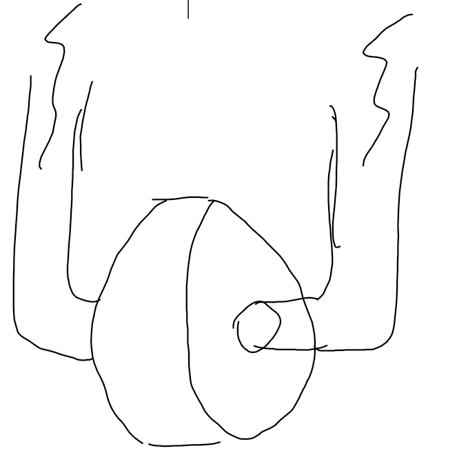
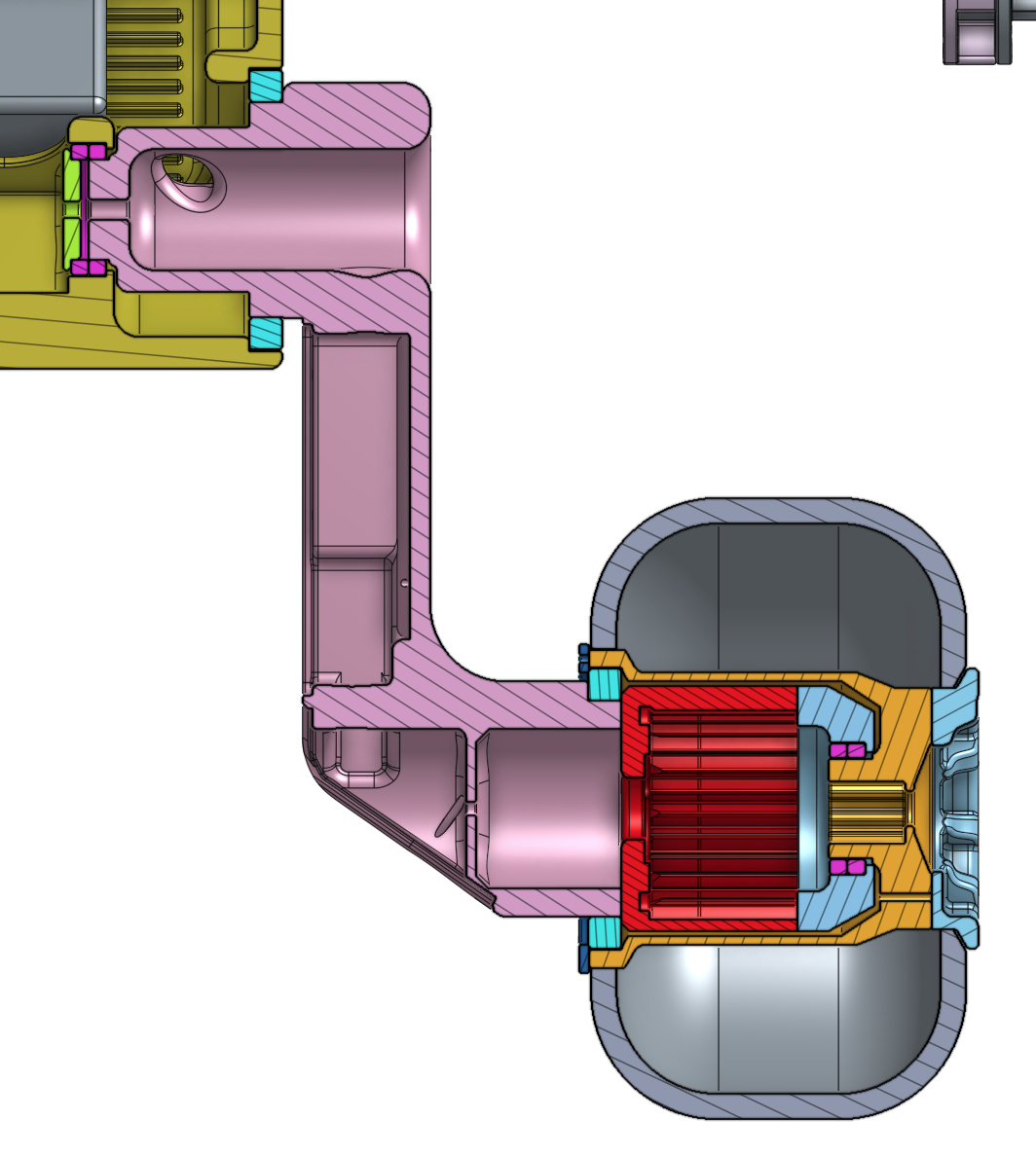
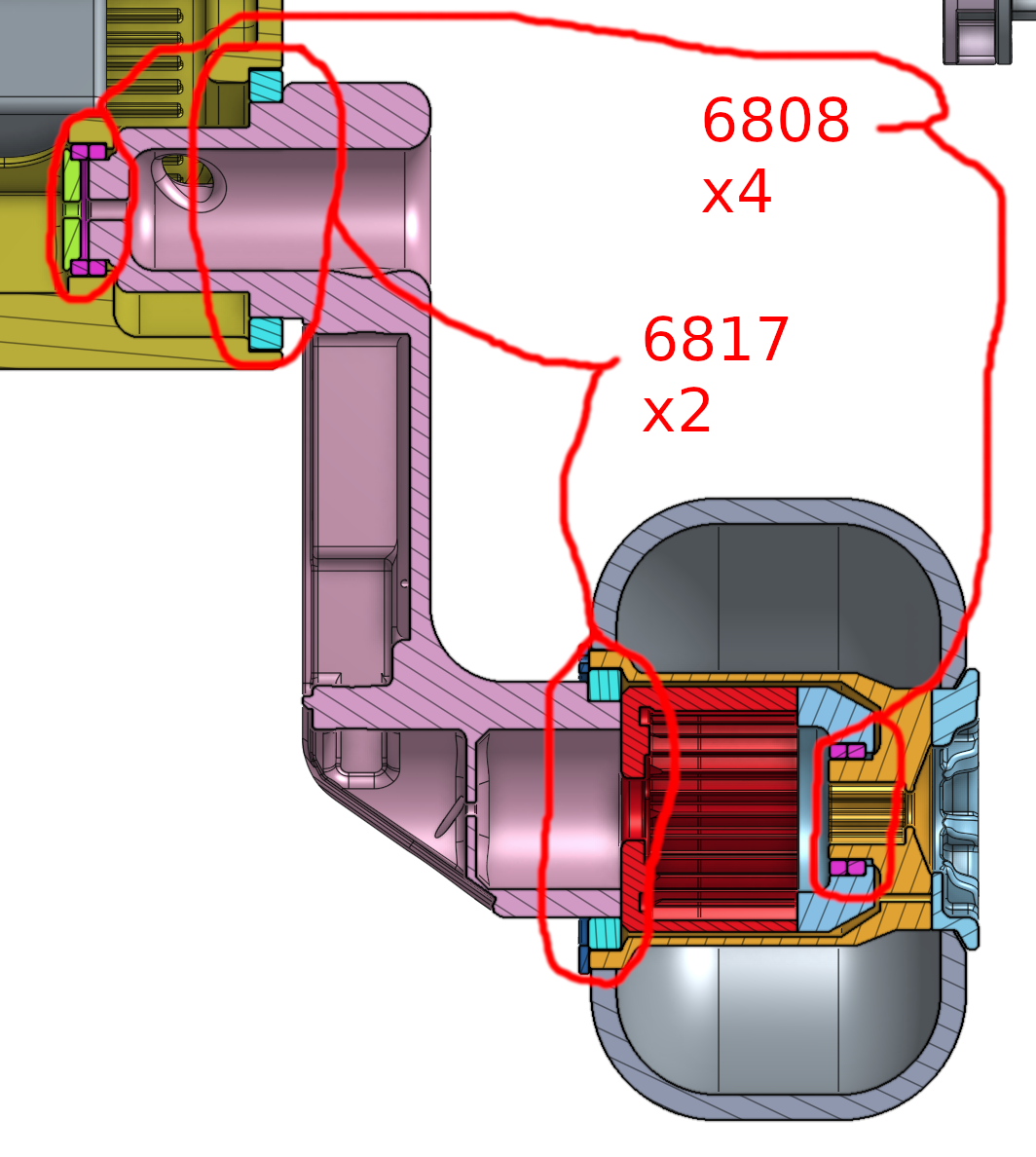
Rover’s suspension geometry of course, has roughly speaking, 2 bearing-type interfaces per independent axle:
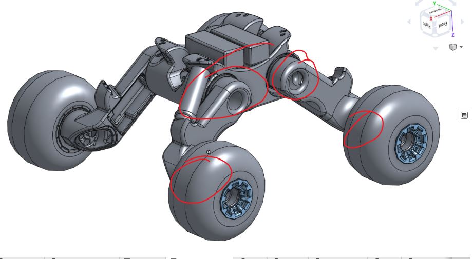
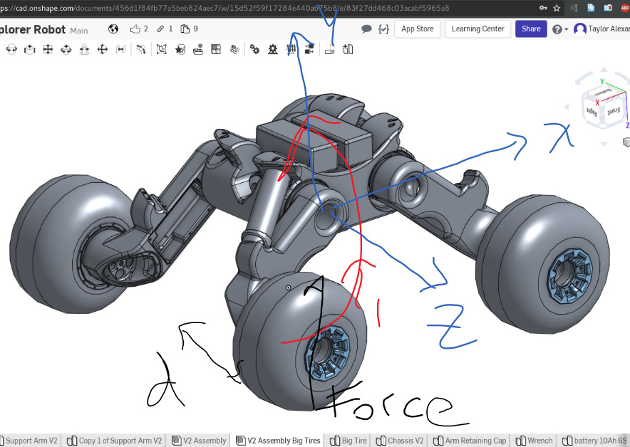
Just considering one of the bearing-type interfaces, you can see that a force on the tire, results in a moment T1 about the x-axis, since the wheel is off-set from the bearing by a distance d:
Is there any way to improve this design? I’ve been playing around with fixed-axle geometry and 4-arm linkage designs in my head… also Macpherson struts and whatnot… but I don’t have any time to CAD or sketch them out.
It is also entirely possible that I am over-thinking this wayy too much… especially since proof-of-concept was shown in Taylor’s video post a few months back. My intuitive concern is that the material of the suspension is 3D printed plastic, and i’m not too familiar with the yield strength of 3D printed materials. My other intuition is that since the drive-train is now effectively contained within each wheel via hub motor (as compared with a normal internal combustion engine driven car), this allows a lot more space to play around with a geometrical solution to this problem. I had a colleague from my previous company, a designer, who said he loved to approach all engineering problems assuming that there is always a geometrical solution to anything.
Would love everyone’s thoughts and opinions on this. Thanks!
Cheers,
Kai
(ps. Hope I figured out how to upload photos nicely here… if there’s an error in the pictures i’ll try post them in the comments or something. )
(pps. Also just thought of a “forked” suspension design as follows, but it really increases the bulkiness of the overall build, so i’m inclined to shy away from this solution: )
")