VESC mods for robotics use

This is just a thread where I can talk about the mods to the VESC motor controller required for use with Rover and subsequent robots.

So far the VESC has been a great motor controller. After making my own in 2016 and realizing I needed larger FETs to handle the high currents low speed control needs, I began to look elsewhere.
D4489BC1-C3C0-488B-94E4-6D4EA2F0E6F94A6448F5-9899-4A57-BECA-0834B5E66084
(Above, my motor controller design from 2016)

As I looked for other designs, I found the ODrive and the VESC. In early 2017 the ODrive was a new product and I backed one of the early batches. I also ordered a VESC to play with. The VESC began to work well for me, and so I have still not reviewed my ODrive board.

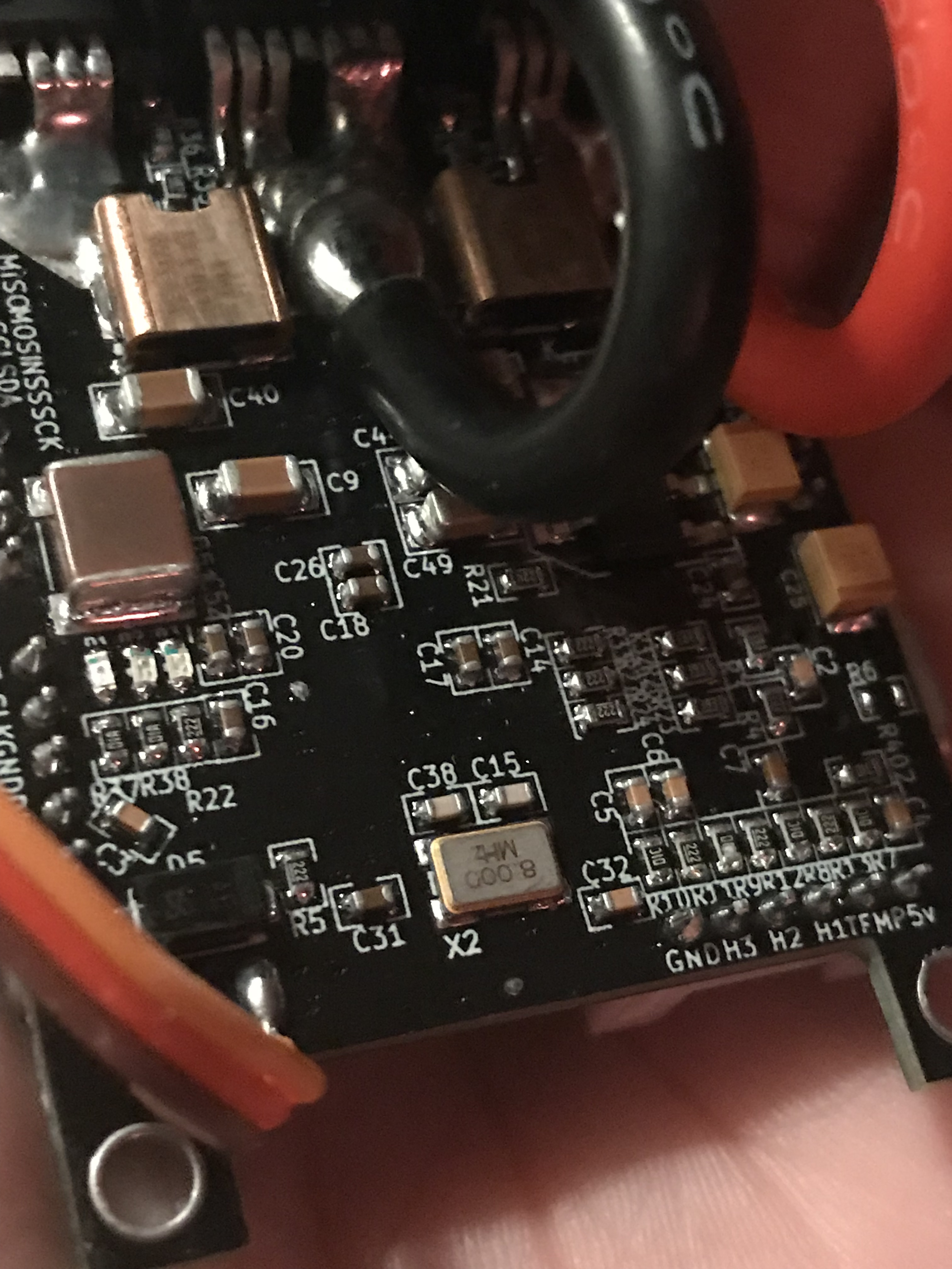
I did find however that the VESC needs a capacitor soldered on to it to make Field Oriented Control mode (a high precision high torque control method) work well. In robotics you often need precision low speed control, and while the VESC is used primarily for electric skateboards and ebikes, Benjamin Vedder the VESC creator has a thing for robotics too. Unfortunately FOC seems to have been added after the hardware was designed and the high rate of switching needed to make it work can prematurely drain the tank capacitors used to energize the FETS. This will trigger the dreaded DRV errors many VESC users encounter. There are many things that can cause DRV errors, but depletion of these tank caps below 8 volts is the one I found I needed to fix. It looks like I failed to take photos of the debugging process but after reading the DRV chips data sheet and probing the board, I determined that the voltage at these caps hit 8v before every fault. Adding a 10uf cap eliminated this condition, which I had been triggering on ramp up every time.

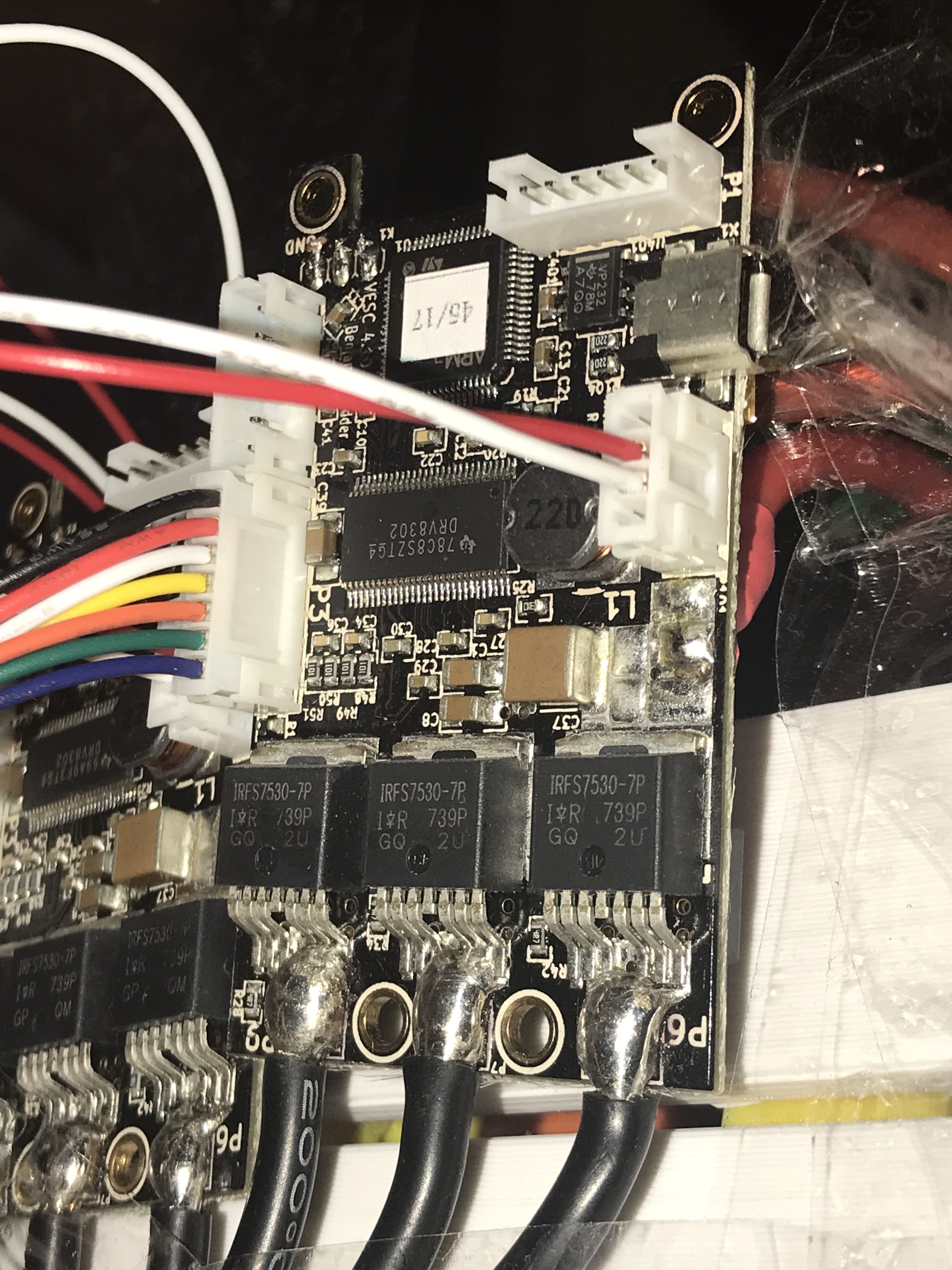
The caps c18 and c26 are too low value and adding a 10uF cap capable of above 20 volts or so (I cannot recall the exact cutoff) is important.

See those caps below:

6730E4DD-06C4-4689-A183-3B8588C5A734

And a modified board here:
2EA74EB0-498E-4C01-BA74-1F346AEEAB09

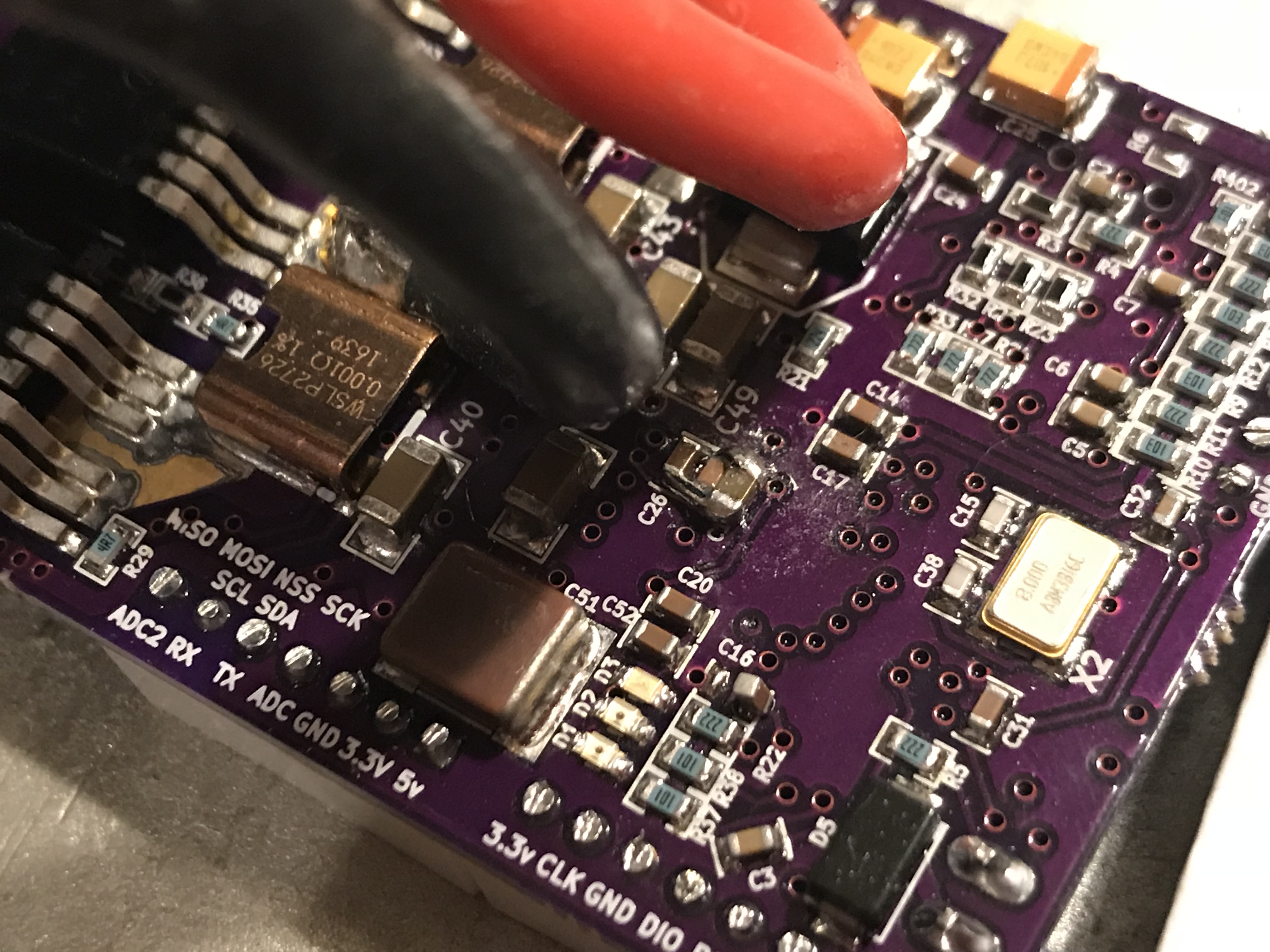
Once this cap is added, my constant DRV issues disappeared, and the oscilloscope confirmed that the voltage here no longer dropped below 8 volts.

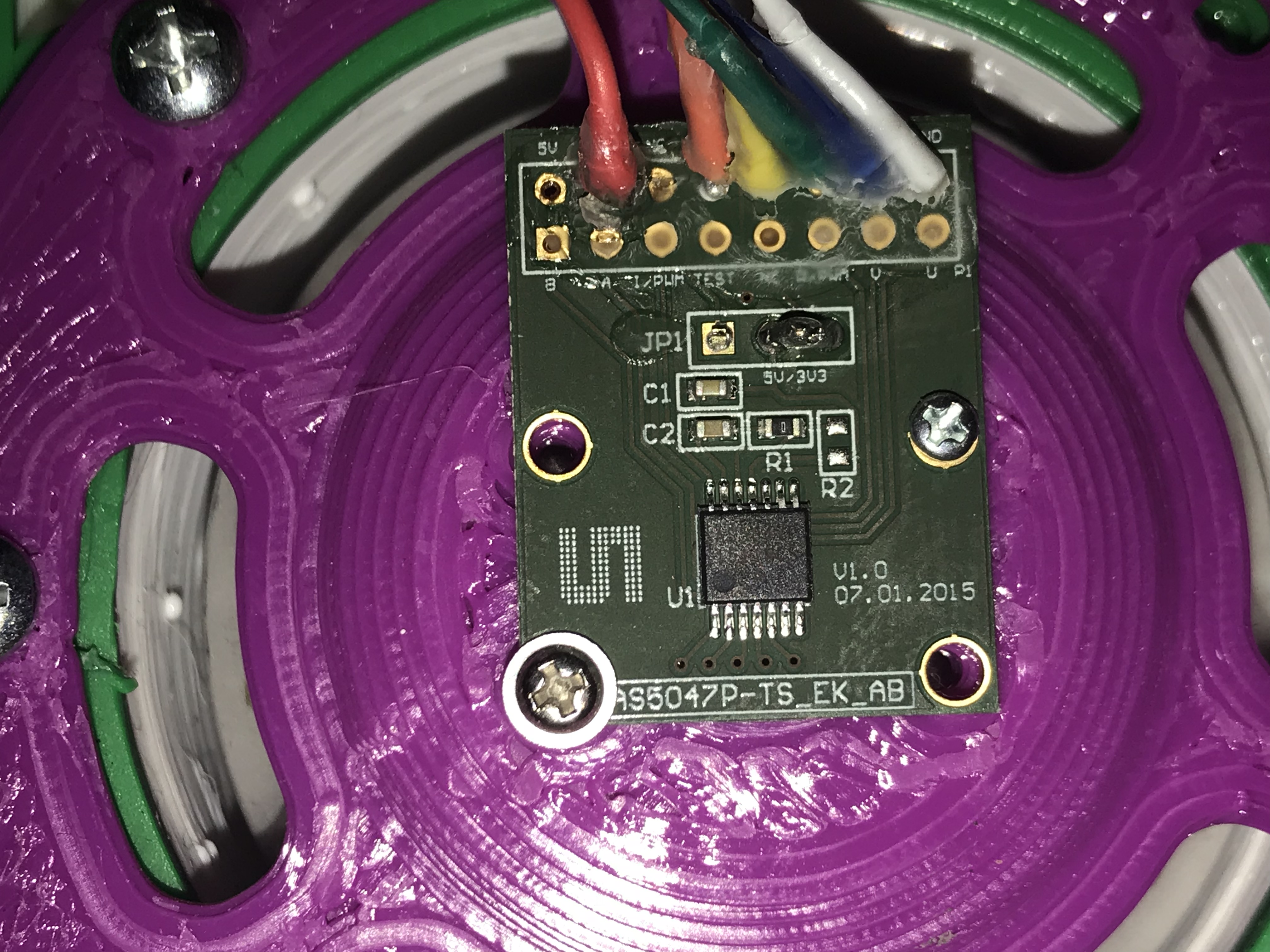
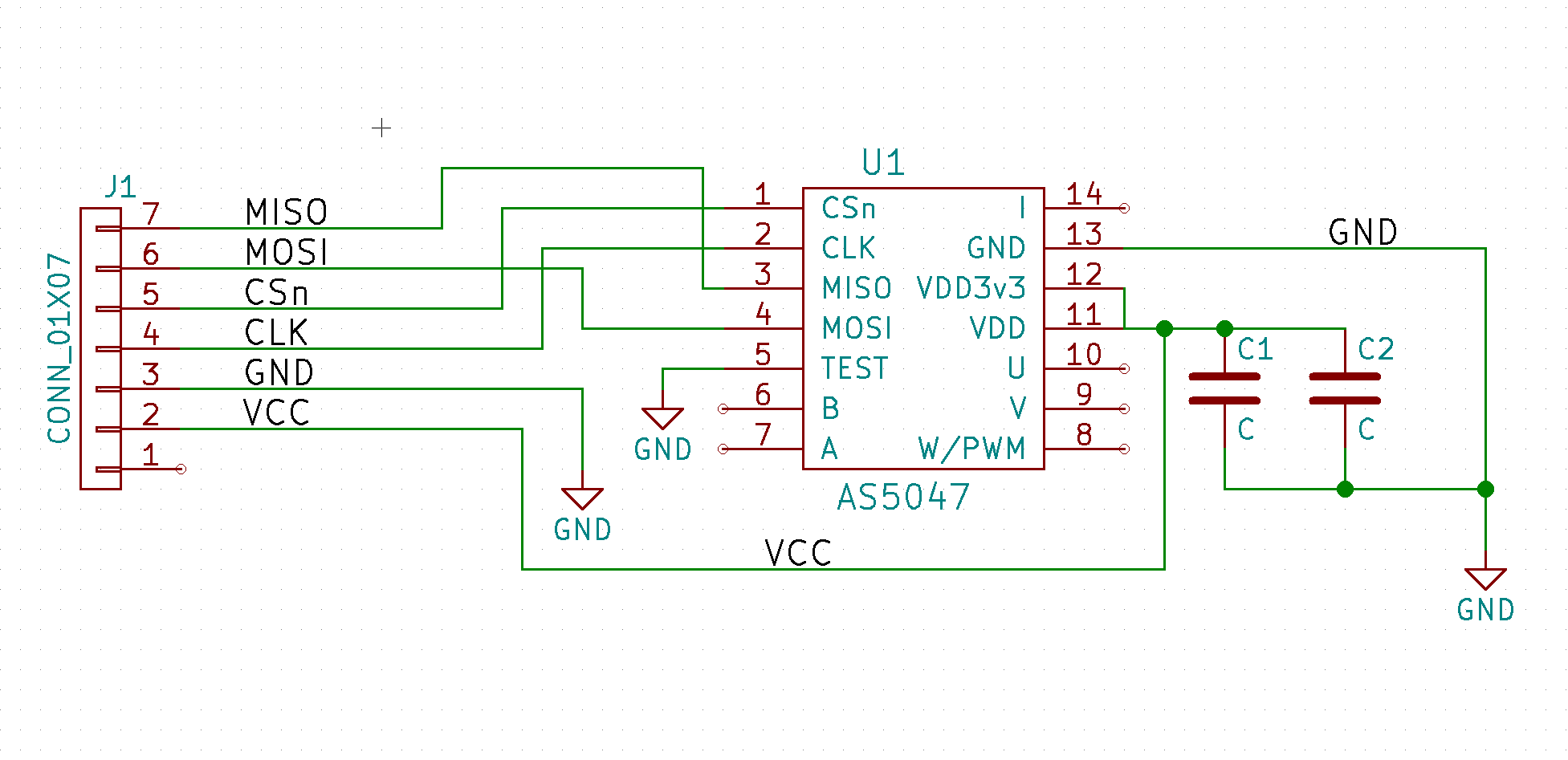
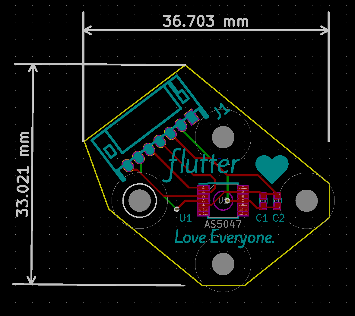
That’s the only mod my VESCs need. Another mod people online have done is to move some resistors around to use an SPI encoder, but there is another port on the board you can use that is faster (hardware SPI instead of software SPI) and does not require mods - just a change in a header file for the firmware.

That’s all I wanted to share for now! I will try to put my scope on a board in the future to share my findings fully.

1 Like

I was recently asked a couple of questions about this via email. I thought I’d post the answers here so everyone can benefit.

The questions were: what pins did you use for hardware SPI and where is this enabled in the firmware?

For the firmware, see the commit in my branch of the VESC firmware with my changes for Rover:

Note in particular the following line:

#define AS5047_USE_HW_SPI_PINS 1

So that’s how you enable hardware SPI, and if you follow that definition in the code, you can see which pins it enables. But below I will also show pictures of the necessary wiring.

I want to point out though that you can just run the Rover firmware from that repo if you’d like - it’s generally compatible with normal VESC operation. I’ve included the compiled binaries in the git repo. It also features a new feature that keeps track of the absolute position of the encoder over many revolutions, and has a new CAN command called COMM_SET_CURRENT_GET_POSITION that sends the absolute encoder position (and velocity I believe) when you send a set_current command. That’s the single command the Rover stack uses for controlling the motors (after the motor has been configured in VESC Tool).

So feel free to give that a try!

But here are the two pictures of Rover that will clarify the wiring:
6544F0C3-B197-4180-B235-F56CF2865D61B803B1F1-D293-4CA0-9DE9-8419B68A0A13

Thanks for reading and feel free to ask any questions if that’s not clear!

==========================================

Update January 26, 2019

I’ve updated the encoder documentation on github, and copied the images below:

The encoder schematic is here:
encoder_schematic

That mates 1:1 with the VESC plug P3. Notably, the encoder is running at 3.3v, 5v is not used.
Here is the PCB I use, which is CC0 and on github - you can make these!
PCB

pcb2

The PCB mates to a 25 x 19 pattern on my Hobbyking 4114-320 motors, or on Rover just goes in to a thin plastic support behind the motor. The 4114-230’s I used are discontinued, but it looks like these are a suitable replacement, albiet with a 5mm shaft instead of 4mm:

Hello, Taylor!

Great for sharing the stuff about VESC and SPI encoders. Most of all I like the Love idea, because we all need a proper inner drive.

I have a situation and I’m a little bit blurry.

  1. For a BLDC taken from an hover board, 6.5" type you recommend using VESC or Odrive? These things I want to connect them with ROS eventually.

  2. Have you seen proper off-axis encoders ideally with absolute indications? I’ve seen something from Allegro, but…

All the best,
Ktysai

1 Like

Absolute encoders don’t seem practical for wheels or motors, where what you always need is relative, like how far did I move. And absolute encoders in general are more expensive.
Absolute coordinates in space would be very valuable, but are very hard to get except in a highly controlled environment like a milling machine, and even there it’s rare to have absolute.

Right, Dave!

My problem is the integration with ROS. There’s needed an absolute encoder, at least at my current level of expertise.

Thanks for sharing!

Hi Taylor,

Can you please clarify wiring the AS5047P sensor board to the VESC? Are you using unidirectional (MOSI not connected) or bidirectional (MISO+MOSI) wiring? I’m curious if we can get away without connecting MOSI and use this pin as RX instead?

-albertr

Interesting!

The short answer is I am not sure. I have both directions wired up, but I don’t recall if we are writing to the chip at all. It may need some initial setup at power on.

I think some firmware changes would be required either way, as the encoder config now I think sets both directional pins as used by the SPI, so they’d be disconnected from serial.

Are you handy with code? Could you read the firmware code and see if we send values to the encoder? Otherwise I will try to take a look. You could also black box it and see if everything works the same with that line disconnected even at power on.

Let me know what you think!

I’m pretty new to VESC, but I’ll try to take a look at encoder.c to see if it does any writing… it would be nice to have both TX/RX pins available for UART applications.

-albertr

Unless I’m mistaken, it looks like the code in encoder.c doesn’t need to write anything to the SPI slave. There’s no device-specific setup and it looks like all it does is constantly reading value of anglular register. However, I didn’t realize that UART TX pin is multiplexed with SPI NSS pin which is used to control Chip Select. I think it might be possible to re-purpose one of the other pins on VESC (hall sensor perhaps?) to control Chip Select instead. If so, then we can use both UART TX & RX pin for serial communication. I’ll try to play with that and will let you know if I can get it to work.

-albertr