Ahoy friend!
So, you want to build a Rover? Wicked! If you do, you’ll be a pioneer in the field of 3D printed robotics!
This guide will give you some details about how to get started.
First, see this mostly complete bill of materials for Rover here:
https://hackaday.io/project/158458/components
Now let’s start with some basics: Rover is a large 3D printed four wheel drive robot that costs about $1500 to build including batteries, printing plastic, electronics and other mechanical parts. Printing Rover V2 as currently designed requires a large volume 3D printer. As designed, Rover needs a minimum print volume of 335mm x 225mm x 160mm, as I designed it based on the TEVO Black Widow printer I have. However the Black Widow requires significant assembly, so I suggest trying something like the 400mm variant of the CR-10 printer.
Some of Rover’s parts can be printed on a typical 3D printer, and if you already have a 3D printer, it’s best to start by just printing those parts. In particular, the gearbox and wheel assembly can be printed inside of a typical 180mm cubed print volume.
Rover is designed in OnShape, so you will need an OnShape account to get the files. Conveniently OnShape is free, though be warned that an Aug 2018 license update now dictates all work done on free accounts is public domain and for non commercial use only. Rover is already public domain and Reboot is non commercial, but if you want to make your own closed fork of Rover a free OnShape account will not suffice.
Sign up for OnShape and follow this link to access the files:
https://cad.onshape.com/documents/456d1f84fb77a5beb824aec7/w/15d52f59f17284e440ab75b8/e/83f27dd468c03acabf5965a8
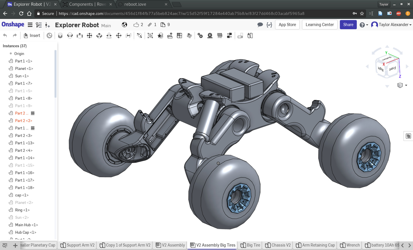
[The Rover Assembly in the OnShape Files]
When you click the link, it might take you to a different component, but all of Rover’s parts can be accessed using the tabs on the bottom of the window. You will need to fork the design (which makes a copy and places it in your account) so that you can edit the files. While you might just want to print Rover with no changes, chances are you’ll end up wanting to adjust a dimension or two as you print. It’s not hard, and it will really make things easier if your printer runs a little differently than mine. I try to design some tolerance in to each part to account for different printers, but I may not always do so perfectly.
Now lets look at what it would take to print the large parts of Rover.
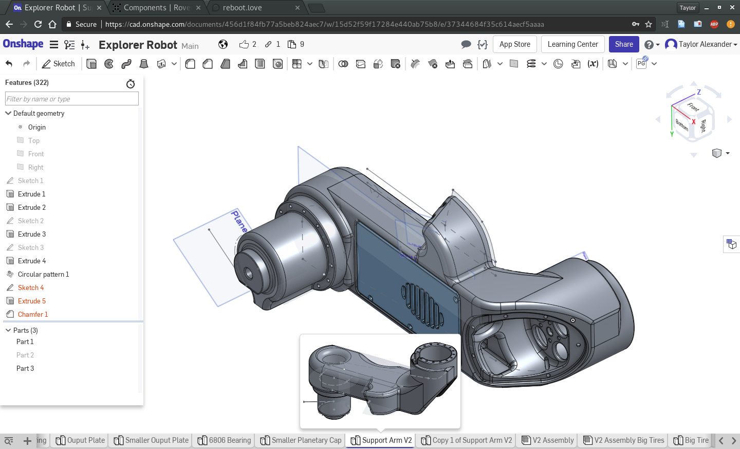
Using the tabs at the bottom of the screen, scrolling left or right if necessary, find the part called “Support Arm V2” and click on it. Something like this should load:
Now make sure the “Parts” section of the window is visible, right click on “Part 1”, and hit “Export”.
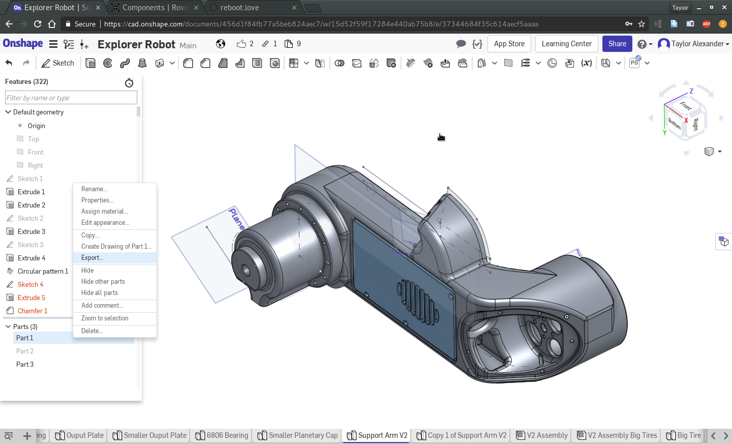
Make sure to select STL and millimeters, as shown here, then hit OK to download the part.

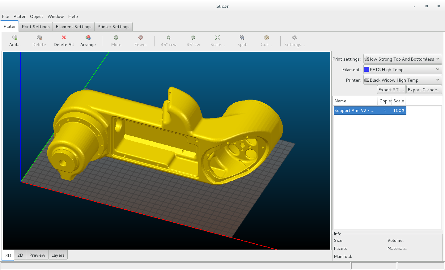
Load the part in to your favorite slicing program, rotate as needed (I had to rotate 90 degrees around the X axis in Slic3r), and voila!
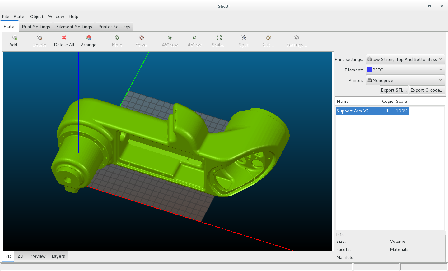
Yeah… the part is too big for your average printer. Here’s what it looks like on the TEVO Black Window:
That’s a better fit!
If you do have a large printer and want to print with a 1.2mm nozzle like I do, you may find some value in the config file I used to print these parts:
These parts take about 29 hours to print each on my TEVO. Print two as downloaded and two as mirror images. Then find the main chassis and print one of those. Look for the part called “Chassis V2”.
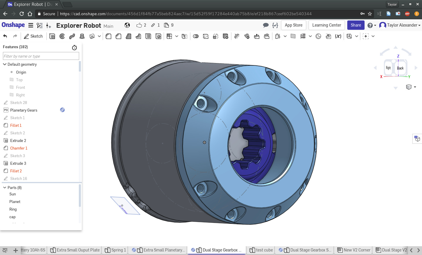
If you don’t have a large format printer, we’ll start with the smaller and in some ways more challenging part of Rover, the gearbox. I’ve gone through several revisions of Rover’s gearboxes, but the current version of interest is “Dual Stage Gearbox Metal Pins Mod 2”. Find that part on the bottom list of parts, or click the magnifying glass on the bottom left of your window to open the tab manager in OnShape, which has a search bar.
Once the gearbox is opened, it may look like this:
Using the “Parts” menu on the bottom left corner of the screen, hide all parts except the Sun, Planet, and Ring. You should now have something that looks like this:
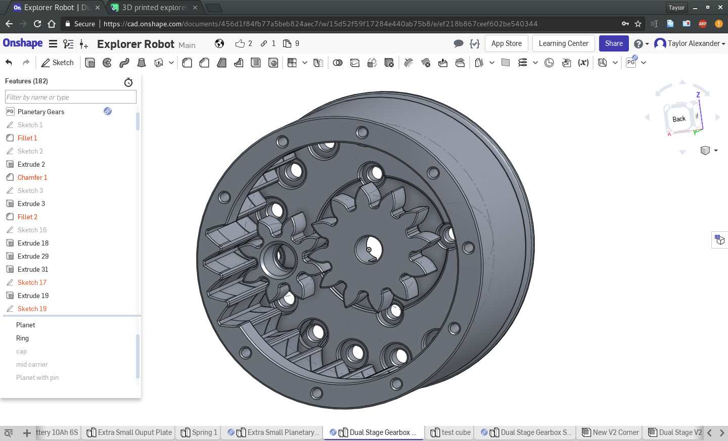
These will be the parts we print first. If you can print these parts properly and they fit together, you’re well on your way to printing your own Rover.
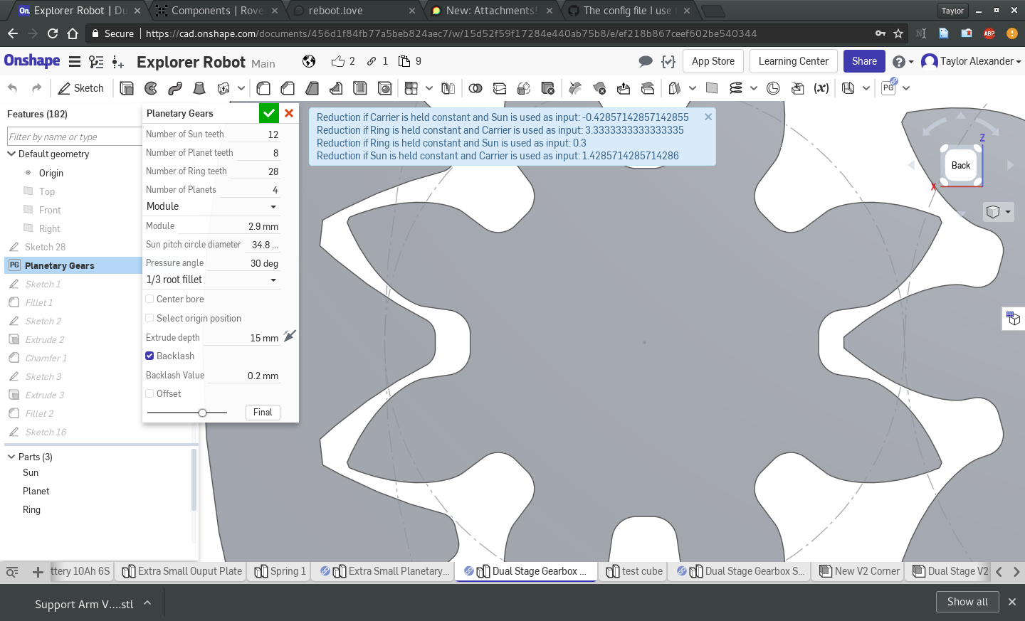
First, lets check the tolerance, which is a critical dimension when printing gears. On the feature tree on the left, scroll all the way to the top, right click on “Planetary Gears” and hit “Edit”. You should see the following screen:
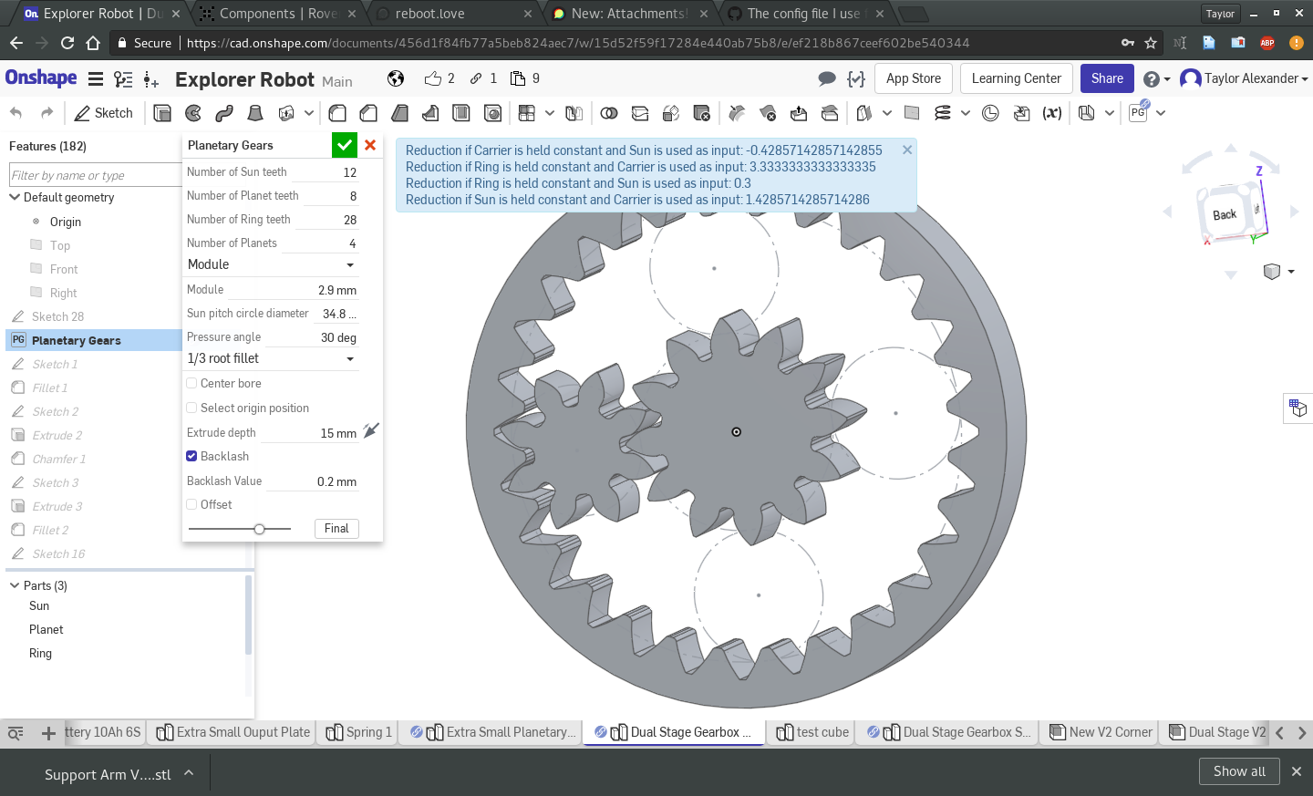
This is where we adjust the key parameters of the gearbox. Most of this you do not want to change, as doing so may make it necessary to manually fix broken parts of the gearbox structure down the line. You can and should explore the effects of that, and if you fork your design or duplicate the tab you can try things out to your heart’s content, but if you just want to get printing now we will examine one key parameter you can change without issue.
We want to examine the “Backlash Value” parameter specified towards the bottom of the parameter list. This determines how much space to add between gears to compensate for inaccuracies in the printing process. No machine makes perfect parts, and 3D printers are often even less accurate than traditional machine tools. Adding some gap around the parts ensures that everything can be assembled properly without being too tight to rotate. If you print the parts with too small a gap, you’ll cause unnecessary friction that heats up the gearbox and causes it to fail. See the difference between 0.2mm gap and a 0.01mm gap in the following images:
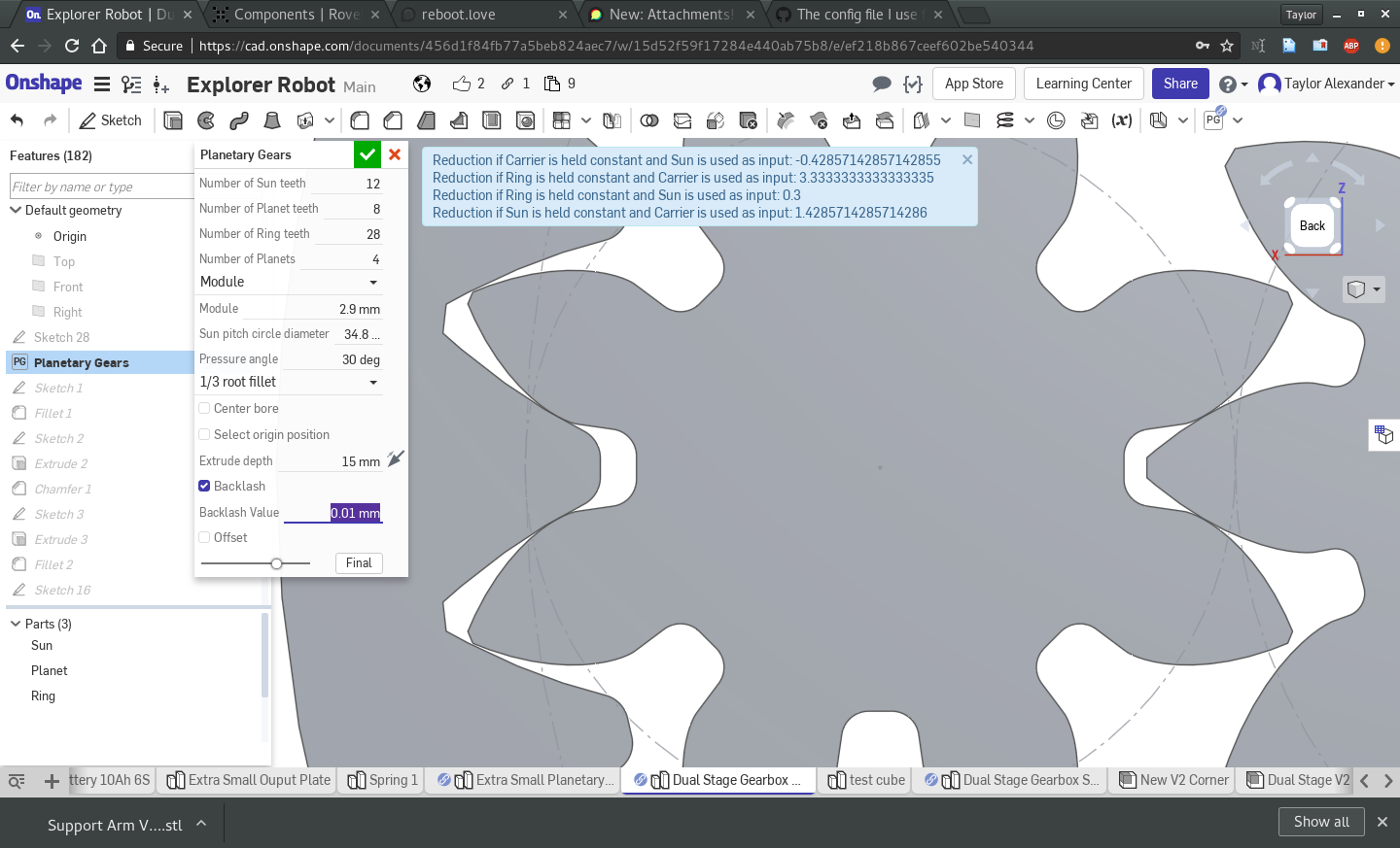
For your first gearbox, it’s far better to err on the side of extra tolerance, so you can see how things fit together. Start with 0.2mm for the “Backlash Value” and hit “OK”. Now wait while OnShape rebuilds the gearbox.
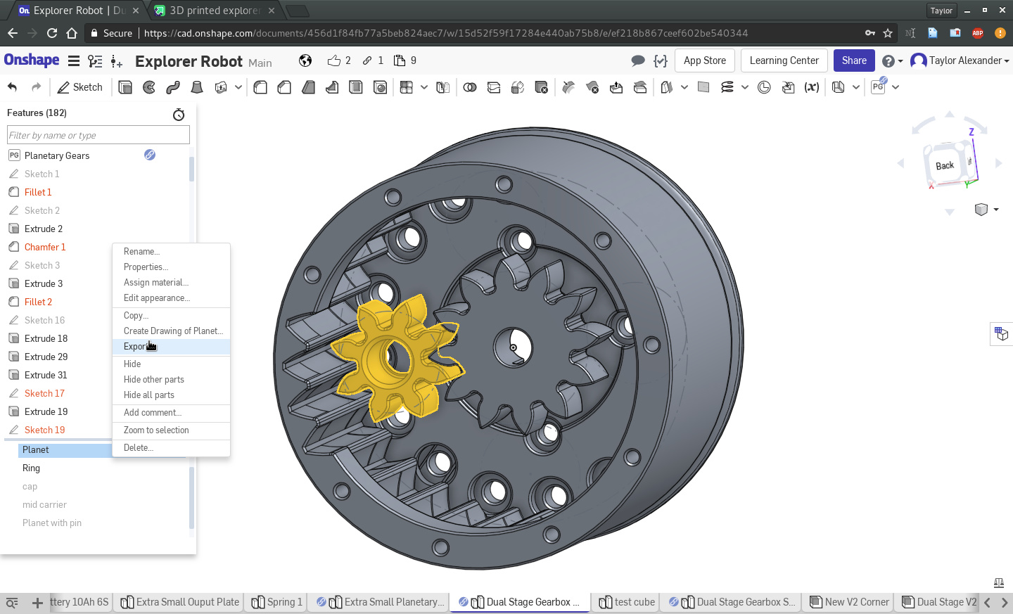
Start by printing the planet, the simplest part of the gearbox. For a complete Rover V2 you will need 32 of these, so get used to printing them. In the main assembly, in the “Parts” window, right click on the Planet and select “Export”.
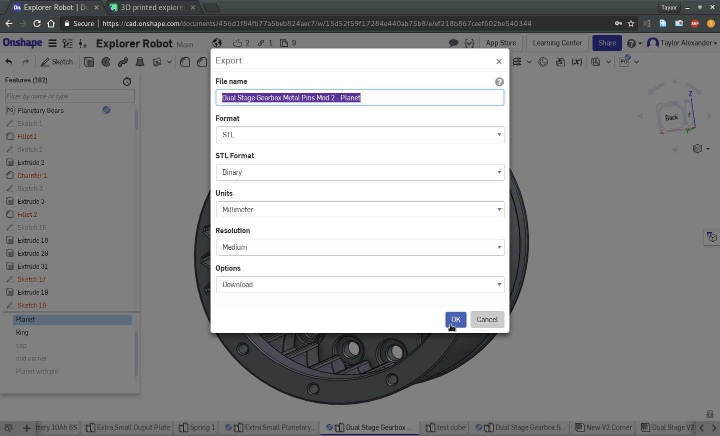
Again, make sure to select “STL” and “Millimeter” when exporting.
Open the part in your favorite slicer. You will need to rotate the part so that the larger hole is facing up, which in Slic3r is 270 degrees around the X axis.
I recommend printing with smaller layers and 100% infill. For my 1.2mm nozzle this is the config I’ve used:
Once you’ve sliced the part, the gcode preview should look something like this:
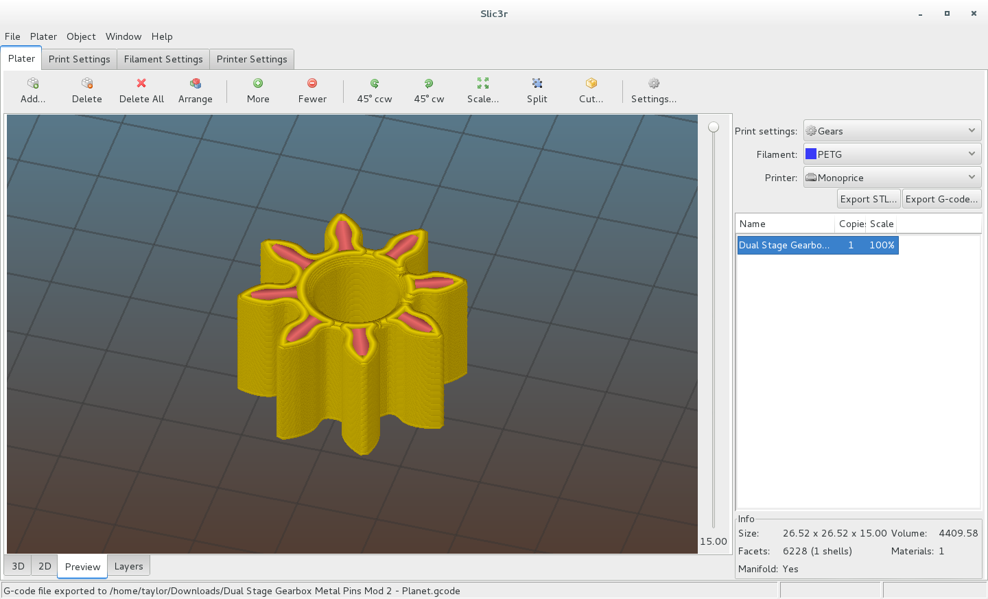
Note that unless you use a 1.2mm nozzle like I do, you will have a lot more paths shown.
Print that part and see how it looks. Was the bed height correct? Do the teeth look clean and consistent?
If everything looks good, print 3 more planets, a sun gear, and a ring gear. Once you’re done, put everything together and see how it looks:
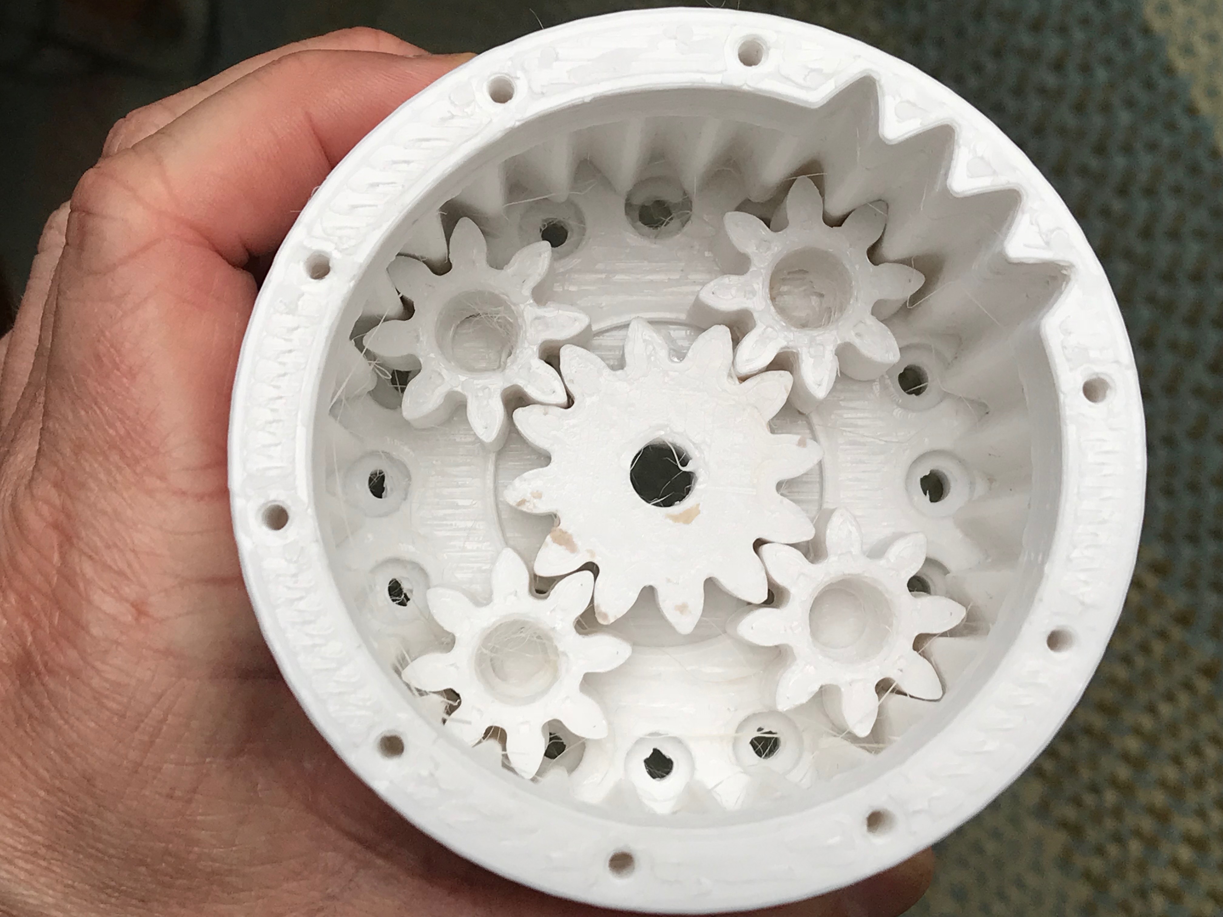
If it looks good, print the mid carrier, output carrier, and cap, and source the required parts. I’ve gotta go for now but I will add the part numbers for the pins and other parts soon. If you get this far or you have any trouble along the way, please let us know here and someone will guide you. Thanks for reading and best of luck!