I want to build a quadruped robot, for that I need to control multiple VESC attached to the CAN bus.
Beaglebone Blue which has CAN, will send out POSITION COMMAND to each VESC individually, and should also read ENCODER value from each VESC independently.
I know that VESC has CAN bus forwarding option which won’t be useful in this case because, they have one master VESC which receives input from ADC/PPM and forwards it to the the remaining VESC.
My question is, Will it be possible to dump the firmware change made in this repository and use the motor.py & vesc.py from rover_control in Beaglebone Bluefor my purpose?
Are you using the AS5047 encoder as mentioned in this post?
If so, you can download the firmware bin file from this folder:
And you should be able to use the motor.py and vesc.py files on your beaglebone. You do need a USB to CAN bus adapter though, since I haven’t written any code to use one VESC as a master using CAN forwarding (my library does not ever talk to the VESC over USB). If you use the CANable USB adapter, the code should run readily.
Note that on the raspberry pi, I run the following command to get the CAN bus working on each run:
ip link set can0 up type can bitrate 1000000
That happens here:
Please let me know if this works for you! I’m happy to answer any other questions!
I’m using AS5145b - (12 bit resolution), so I just changed the 16384 into 4096 and then built it and flashed it in VESC.
I have also installed all the dependencies needed to run motor.py and removed motor1 instance(I just want to control 1 motor initially) , [Beaglebone Blue has internal CAN], Then i configured my CAN bus and when i do:
sudo python3 motors.py can0, I get the following output:
Start Motors
MotionControlThread started!
Zero motor 0
Motor0 actual Velocity: 0 Command: 500 .
Motor0 actual Velocity: 0 Command: 500 .
Motor0 actual Velocity: 0 Command: 500 .
Motor0 actual Velocity: 0 Command: 500 .
Motor0 actual Velocity: 0 Command: 500 .
Starting motors GRPC server...
Motor0 actual Velocity: 0 Command: 163 .
Motor0 actual Velocity: 0 Command: -8 .
STARTED MOTORS GRPC SERVER
Motor0 actual Velocity: 0 Command: 7 .
Motor0 actual Velocity: 0 Command: 8 .
Motor0 actual Velocity: 0 Command: -12 .
Motor0 actual Velocity: 0 Command: -11 .
Motor0 actual Velocity: 0 Command: -11 .
Motor0 actual Velocity: 0 Command: 24 .
Motor0 actual Velocity: 0 Command: 0 .
But the Motor is not spinning smoothly and makes some sounds(as seen in these video1, video2). How to make the motors spin smoothly and How to set a particular position value?
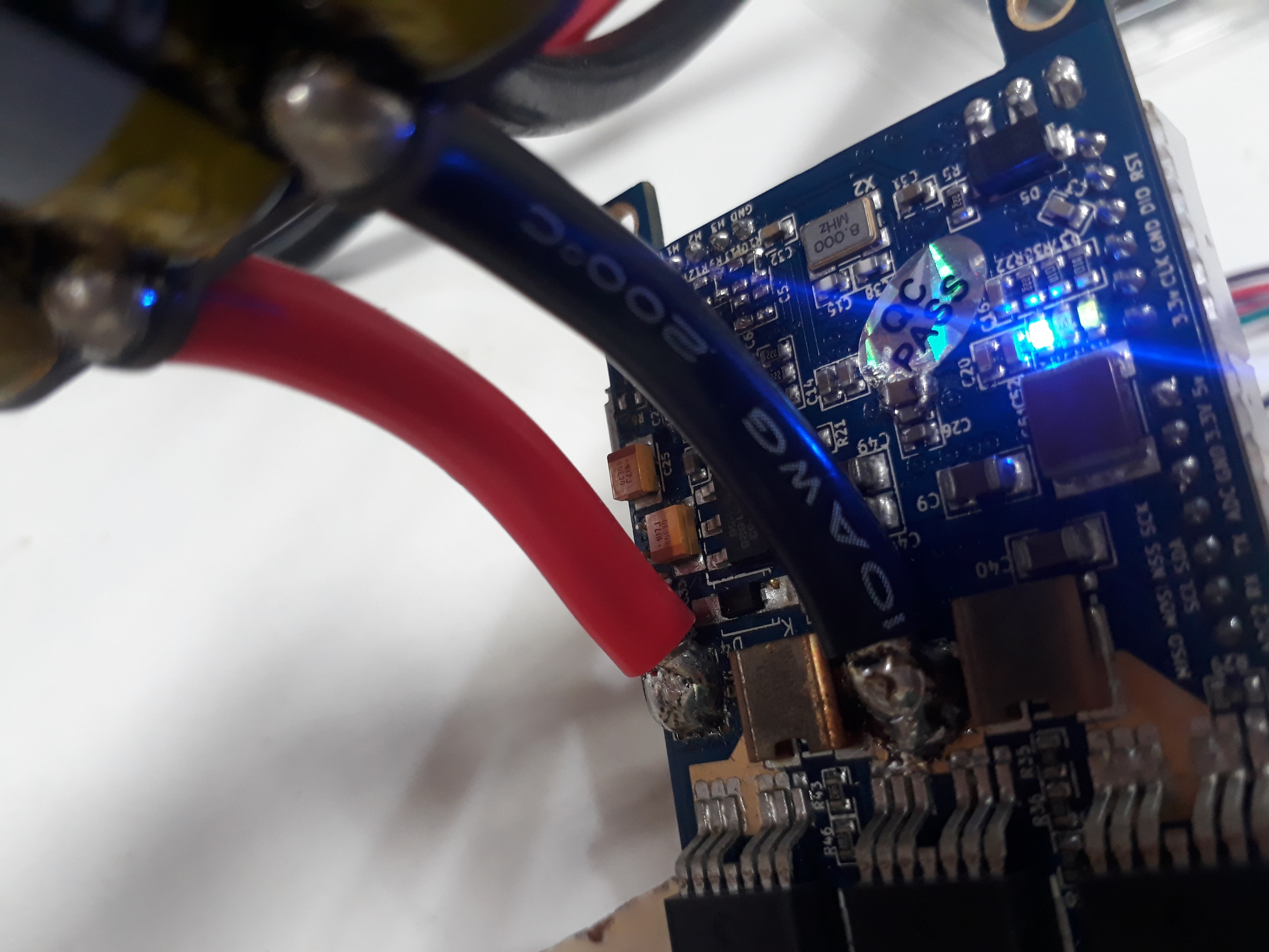
I think your VESC might be going in to fault because of this issue:
Have you added that capacitor?
Also in the motors.py, look for these values:
MAX_CURRENT = 10
MAX_BRAKE_CURRENT = 1
P_SCALAR = 1/250.0
D_SCALAR = 1/100.0
You will need to adjust those values for your motor. Lower current and smaller scalar values will be less likely to trigger the fault. Try setting the max current lower to see if the fault goes away.
But if you haven’t added the capacitor as in the linked post, you may need to.
Will remove those caps and will let you know, how it worked.
To make the motor to spin at desired velocity, I set self.velocity_command = 500 in motor.py but once the gRPC server started, How the command value changed to163, and then Why the command value keeps on fluctuating ? (It should be same) Whereas actual velocity remains zero, when it has to increase from zero to desired velocity?
Am just running motor.py , Is there anything, am doing wrong?
(I am sorry to ask you so many question, My background in Mechanical and I have just started to learn embedded system for robotics)
First of all, you need to add a capacitor, not remove any.
As far as the code, you might want to remove the GRPC server code, or comment out the part where it manipulates the values. I don’t know why the command values would fluctuate, but I would expect the measured values to fluctuate.
I might need to make a simpler version of motors.py to help with this. But for now, add that capacitor and/or lower the current and see if that helps!
Can you tell me how to read the encoder value and to set the motor velocity alone?
Based upon your frist commit, I created a simple_control.py (without grpc server) it doesn’t work yet.
It would be really great, if you give some insight on how to write simple script to control velocity and read the encoder value. (Maybe share simple code which does that alone?)
Oooh! I remembered, you need a program called vesc_tool. I think I have a repo, but it’s also on GitHub via google. I should make a tutorial, but if you can find that program and run it, let me know. vesc_tool is free and open source, and is used to calibrate new motors. That’s what you use to confirm the encoder is working and to save in calibration values for each motor. Use that to configure the motor and to ensure your commutation values are correct.
I can (and should) explain in more detail, but do let me know if you have any trouble finding the program!
And here’s the binary and code for the specific fork of vesc_tool I use, as well as some important XML config files.
If you run Debian or Ubuntu it’s possible that the compiled binary in that folder (use the _87 variant) runs for you, so try that. Otherwise you may need to compile. When you connect, ignore the warning about firmware versions, then load in any of the app and motor XML files in that folder, then adjust it for your motor. It’s easy to use, and an important step. Note too in the app config near the CAN bus ID there is a setting for timeout. For safety it is 10ms during operation but for testing over USB I use 1000ms there. That lets you spin it using vesc_tool, see the encoder live, etc. then when you’re all done, move it back to 10ms for safety, or whatever interval fits for your CAN bus packet interval.
Hopefully that all makes sense, but if not do let me know. I should make a tutorial on this, as with all of the parts.
But I was using the 6 PIN port near the USB port where I removed the PULL-UP resistors to work in ABI mode. But in some forums they have mentioned to use this port for SPI too…!
My question is which is the correct port for reading the encoder in SPI mode? In some forums they suggest to use H1, H2, etc… and I saw you were using the another port?
I cloned your vesc_tool repo and ran vesc_tool_0.87 on my Lap(Ubuntu 14.04), I got the following error: ./vesc_tool_0.87: error while loading shared libraries: libOpenVG.so.1: cannot open shared object file: No such file or directory
The vesc was connected dirtely via the USB port and it has same firmware you had.(expect the places where 16384 was there, I changed to 4096)
When I tried to run VESC_tool from Benjamin Website, I got limited mode, where I could only dump new firmware…!
My firmware is set to use the second port (as shown in my photos and video), as no resistors need to be removed and the VESC can still read halls if desired (AFAIK).
If my binary doesn’t run, its because it was build with different packages. If you rebuild my code on your machine, it will run in the full communication mode. VESC_TOOL is picky about versions. We may need to make a rolling firmware release to support their latest tool, but I just stick with a fixed version for now.
Can you try to build it and report how that does? I don’t remember all what needs to be installed, but if you record what you learn here it will help others. I can advise if you have questions!
The pre compiled vesc_tool_0.87 raises dependency errors. As you rightly pointed out, we have to recompile the source. But for successful build, we have to edit the Makefile and add the correct path to the qmake . For an example, change the /opt/Qt/5.9-stable to /opt/Qt/5.9.2/gcc_64.
After this, just ‘cd vesc_tool/’ and run ‘make’.
I was able to configure motor parameters from the vesc_tool. It was running smoothly during configuration of R, L, Lambda and encoder offset.
After that, the motors didn’t spin smoothly and also the encoder reading was not coming properly, as you can see in this video
I’m not using AS5047, I’m using AS5145b and I just changed 16384 into 4096, is that causing this problem?
When I touch the rotor, it feels like there is a brake current applied and whenever I try to spin it, both of them make the noise which you can hear form the above mentioned link.
It would really helpful if you make tutorial on this issue and also write a python script to control it, without using an gRPC server.
Did you find the encoder calibration step in the software? After you calibrate the encoder, make sure to apply the calibration and then use the buttons on the right side of the program to save the values to the VESC.
Otherwise I can look more in to the different encoder.
Thanks for the note on building vesc_tool!
A simpler motor script would be helpful too. I’ll take contributions from others but I can make one when I have time if no one else does. I’m hoping to make more tutorials in the coming months.